


Description

Introduction
The Full-Wave Rectifier is a fundamental circuit in electronics that converts the entire AC waveform into DC, offering greater efficiency than the Half-Wave Rectifier. It utilizes both the positive and negative halves of the AC cycle, providing smoother and more consistent DC output. This system is widely used in power supplies and other applications where reliable DC is required.
System Components
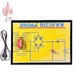
- Diodes (2 or 4): The key components that allow current to flow in one direction, used in a bridge or center-tapped transformer configuration.
- Load Resistor (Rₗ): Represents the device consuming the rectified output.
- AC Supply: Provides the alternating input voltage.

Working Principle
The Full-Wave Rectifier operates on the principle of utilizing both halves of the AC waveform:
- Positive Half-Cycle: In the first half-cycle of the AC input, two diodes conduct and pass current to the load resistor.
- Negative Half-Cycle: During the second half-cycle, the other two diodes conduct, allowing current to flow in the same direction through the load resistor.
This results in a continuous DC output with no interruptions, providing smoother current compared to the Half-Wave Rectifier.
Applications
This system has wide-ranging applications, including:
- Power Supplies: Provides efficient DC for various electronic devices.
- Signal Demodulation: Used in radio receivers to convert AM signals into audio signals.
- Electronics Education: Helps students understand full-wave rectification and its advantages over half-wave.
For more details about the product,
please reach out to us at:
Phone: 8130231489
Email: support@electricalbro.in
We’re here to help!


Reviews
There are no reviews yet.