

Description
Introduction
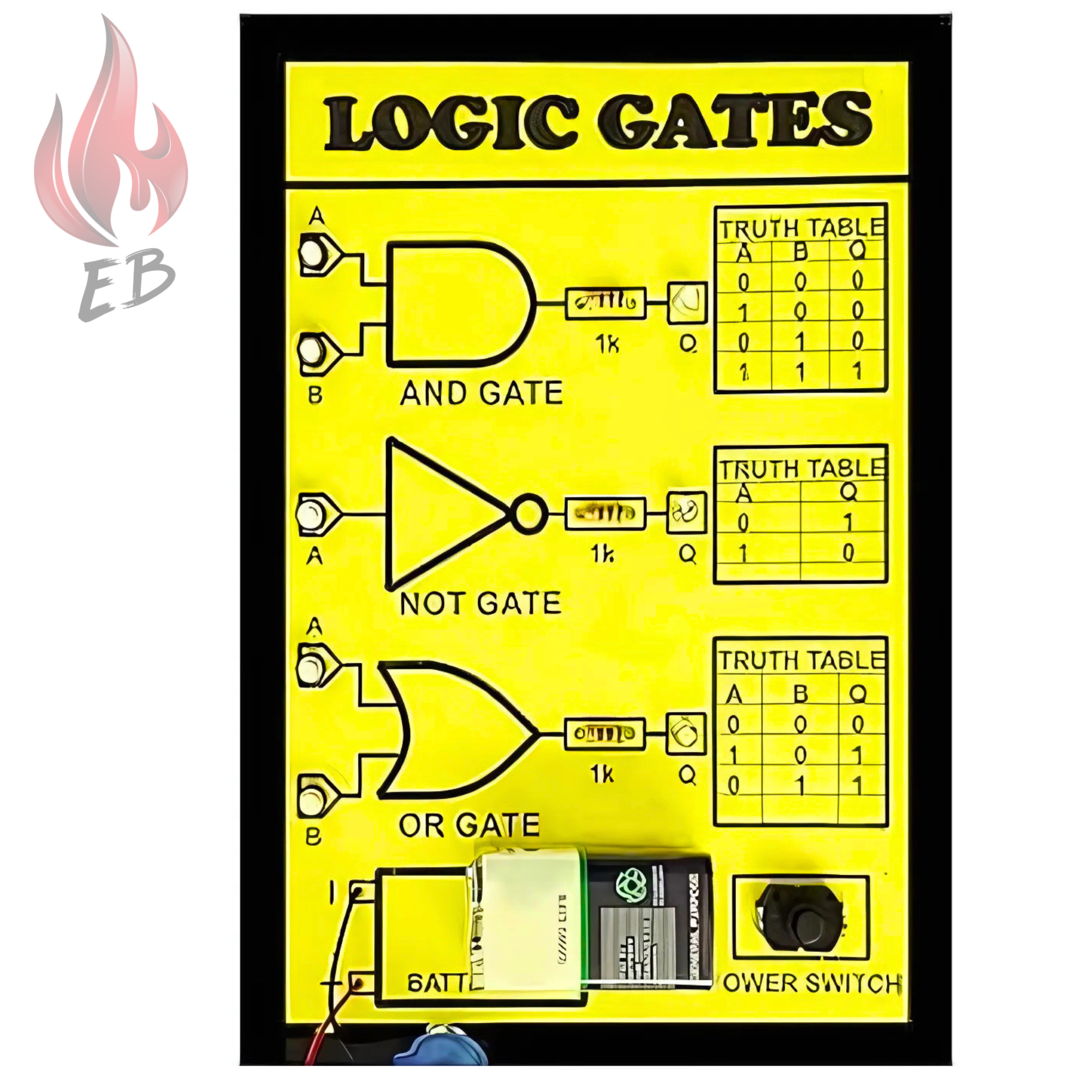
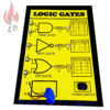
This project introduces the basic Logic Gates: AND Gate, OR Gate, and NOT Gate. These gates are essential components in digital electronics, performing simple logical operations on binary inputs to produce specific outputs, and forming the foundation of digital computing systems.
System Components
- Input pins (2 for AND/OR, 1 for NOT)
- Output pin
- Diodes (for AND/OR gate implementation in some designs)
- Resistors (for current limiting and control)
- Transistors (used in NOT gate design)

Working Principle
-
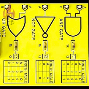
- AND Gate:
- Outputs 1 only when both inputs are 1.
- Truth Table:
Input A Input B Output 0 0 0 0 1 0 1 0 0 1 1 1
- OR Gate:
- Outputs 1 when at least one input is 1.
- Truth Table:
Input A Input B Output 0 0 0 0 1 1 1 0 1 1 1 1
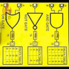
- NOT Gate:
- Outputs the opposite of the input (inverts it).
- Truth Table:
Input Output 0 1 1 0
- AND Gate:
Applications
- AND Gate: Used in control systems, decision-making circuits, and logical operations.
- OR Gate: Employed in circuits where any condition being true should trigger an action, like in alarm systems or security checks.
- NOT Gate: Essential in circuits that require inversion, such as flip-flops, inverters, and buffers in digital electronics.
For more details about the product,
please reach out to us at:
Phone: 8130231489
Email: support@electricalbro.in
We’re here to help!


 BO Motor Wheels for Robotics and DIY Projects
  E88 Drone with 4K Camera WiFi FPV 1080P HD || Dual Foldable RC Drone || Altitude Hold Headless Mode || Visual Positioning Auto Return App Control Multicolor (E88-Single-Battery)
  MAX31865 PT100-PT1000 RTD Platinum Resistance Temperature Detector Module
Reviews
There are no reviews yet.